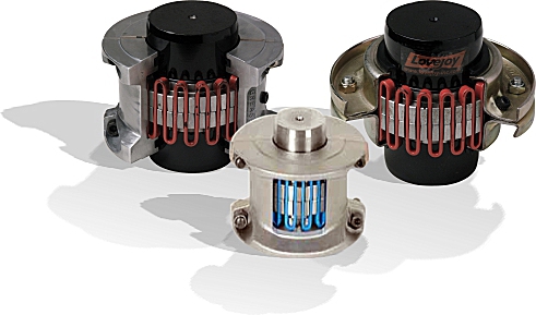


Quick installation and easy maintenance reduces labour and downtime costs.
Fully interchangeable with industry standards. Versatile stock; metric and imperial size cover fasteners available.
High tensile, shot-peened alloy steel grids and precision machined hubs ensure superior performance and long life.

» Ideal for limited space.
» Allows easy access to the grid spring.
» Well suited for reversing applications.
» Lightweight die-cast aluminum grid cover.

» Ideal for higher operating speeds.
» Allows easy access to the grid spring.
» Cover is manufactured from stamped steel for strength.

» Drop-out design ideal for pump applications & servicing.
» Stock sizes 1020 thru 1090.
» Lightweight die-cast aluminum grid cover.

» Offers additional BSE dimensions.
» Lightweight die-cast aluminum grid cover.
Grid couplings from jbj Techniques reduce vibration by as much as 30%, and cushion shock loads to safeguard your and equipment.
The flexible nature of the spring-like grid absorbs impact energy by spreading it out over time, thus reducing the magnitude of the peak loads. This is possible because of the progressive contact that occurs between the curved profile of the hub teeth and the flexible grid. Therefore, as the load increases, more of the tooth comes into contact with the grid, thus supplying superior protection and supreme performance.
Our grid couplings are designed for versatility. Common hubs and grids are used within a given size range for both horizontal and vertical split cover models. Grid installation and replacement is a “snap” at only a fraction of the complete coupling cost.
Made from high tensile alloy steel, the grid spring is carefully formed to shape, then hardened and tempered under controlled conditions. Next, the grids are shot-peened, compressing the surface molecules and leaving a residually stressed surface. This process creates a stronger surface in compression.
Any load applied on the coupling in operation must first surmount the compression forces created by peening before the tensile stress reaches the grid. This provides a dramatic increase in rating over other coupling types, increases reserve strength for longer life and may permit selection of a smaller coupling, thus reducing cost.
1) Determine the application torque using the formula calculations shown on page 5 of the Grid Couplings catalogue.
2) Select the Service Factor from the charts on pages 7 and 8 of the Grid Couplings catalogue. For applications not displayed use the chart shown on page 6. Determine the Selection Torque using the formula shown on previous page.
3) Using the selection torque as calculated, refer to the Performance Chart on page 10 to determine the minimum size grid coupling that will accommodate the torque.
4) Compare the maximum bore for the size selected and ensure the required bore sizes do not exceed the maximum allowable. If the required bore size is larger, step up to the next size coupling and check to see if the bore sizes will fit.
5) Using the selected coupling size, compare the bore and keyway sizes with the charts located on pages 16 to 17 for UPC part numbers.
