Disc Couplings

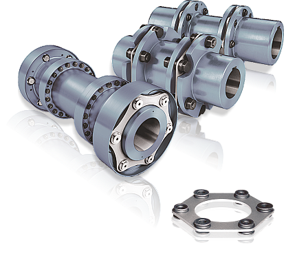
jbj Techniques offer a wide variety of superior torsionally rigid disc coupling products in models designed to meet the application needs of today’s worldwide mechanical power transmission market.

Disc type couplings for mechanical power transmission available from jbj Techniques Limited

Below you will find:
» Attributes of the disc coupling range.

» Steps in selecting a disc coupling.

» Application service factors selection data.

» Technical specification catalogue.

» Fill in work sheet for help to specify coupling.

Backlash-free, torsionally rigid, all-steel, multi-plate couplings. Torque capacity up to 2,000,000 Nm.

Complies with the current ATEX Directive for:
II 2G Ex h IIC T6 ... T2 Gb X
II 2D Ex h IIIC T85 °C ... 250 °C Db X
I M2 Ex h Mb X
These disc couplings utilize disc packs with 6, 8 or 10 bolt designs. Used wherever reliable torque transmission is called for, even in cases of often unavoidable shaft misalignment.

They are universally applicable over a temperature range of from -50°C (or even as low as -60°C on request) up to +280°C, are torsionally rigid, free of torsional backlash and enable quiet running at a constant angular velocity. They are wear-free and maintenance-free and, if correctly fitted, can be expected to have an unlimited service life.


An optimised plate pack and a reworked component part design enable even higher torques and speeds to be transmitted.
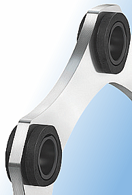
Disc coupling plate pack
In use worldwide ~

Power Generation: air condensers, generators, gas turbines, cooling towers, water turbines, boiler feed pumps.

Pulp & Paper: waste paper, wet section, dry section, smoothers and cylinders, reel winders, coating machines, colanders, wastewater purification plants.

Cranes: hoisting and luffing gear systems, slewing gear systems, trolley and travel gear systems.

Marine and Shipbuilding: single-engine ships, multi-engine ships, dredgers, generator gearboxes, installation vessels.

Petrochemistry: pumps, fans, compressors, air condensers, jack-up rigs, driers, mixers, cooling towers, agitators, reactors, installation vessels.

Water and Wastewater: pumps, aerators, water screw pumps.

Attributes of the Disc Coupling Range:

»  Eliminates the need for lubrication and coupling maintenance.
»  Coupling can be inspected without disassembly.
»  Condition of disc packs can be inspected with a strobe light while the machine is running.
    (Note: It is not recommended that couplings be operated without coupling guards.)
»  Easy to assess equipment misalignment.
»  Torsionally rigid without any backlash.
»  No wearing parts.
»  Resistance to harsh environments.
»  Long life when properly sized and aligned.
»  High power density (higher torque for a given outside diameter).
»  Meet the requirement of API 610. Couplings in accordance with API 671 are also possible.
»  ATEX Certified on request.

Recommended Information Needed to Specify a Disc Coupling from jbj Techniques Limited:

The following information should be provided when placing an order to ensure the proper selection of the disc coupling:
»  Application and type of duty.
»  Type of driver (engine, motor, turbine, etc.)
»  Power and speed.
»  Type of driven equipment.
»  Shaft sizes and separation.
»  Space limitations for major diameter and length.
» Type of fit (Interference fit default, clearance fit and shaft locking device preparation available upon request).
» Special requirements (vertical mounting, drop out center, flange mount, electrically insulated, API-610 up to 3,800 rpm, shear pins, balancing, etc.)

Steps In Selecting A Disc Coupling:

1) Determine coupling type suitable for application. Angular, axial and parallel misalignment properties need to be considered. Size will be determined by the selection torque and shaft diameters.

2) Next, calculate the application torque and apply the service factor to calculate the selection torque. For service factor table see below (hit this link to get there quicker).

Application torque  Nm = (kW x 9550)
RPM

Application torque x service factor = selection torque

3) Use the relevant table on the relevant page (link) for model of coupling for torque rating and shaft size. Sometimes to have the right bore size it may be necessary to have a coupling with more than sufficient torque capabilities.

4) Ensure selected coupling has sufficient speed rating using tables provided.

5) See page 5 (link) for permitted shaft misalignment.

Application service factors selection data:

1} Select the driving machine service factor SFD(link) from Table 2 (below).
2} Select the driven machine service factor SFA(link) from Table 1 (below).
Care should be taken when the driving machine is other than a standard electric motor or turbine. Some engines will impose extra fluctuations on the drive system and allowance should be made accordingly. Please refer to Table 2 (link).

A torsional coupling may be required for diesel drives.

The two service factors SFA and SFD must be added resulting in the combined service factor SF.
SF = SF
A + SFD

Driven Machine Service Factor SFA Table

Driven equipment SFA
BLOWERS, FANS . . . .
Centrifugal 1.0
Lobe / Vane / Turboblowers 1.25
Forced draught fans 1.5
Induc.draught with damper 1.5
Induc.draught without control 2.0
Cooling towers 2.0
CHEMICAL INDUSTRY . . . .
Agitators (thin liquid) 1.0
Agitators (viscous liquid) 1.5
Centrifuges (light) 1.25
Centrifuges (heavy) 1.75
Mixers 1.75
COMPRESSORS . . . .
Centrifugal 1.0
Lobe/Rotary 1.25
Turbocompressors 1.75
Reciprocating:
1 to 3 cylinders 3.0
4 or more cylinders 1.75
CONVEYOR, HOISTS1, ELEVATORS1 . . . .
Conveyors:
Screw / Apron / Belt / Chain 1.25
Bucket / Rotary / Lifts 1.5
Reciprocating 3.0
Hoists:
Medium duty 2.5
Heavy duty 3.0
Elevators:
Centrifugal and gravity disch 1.25
DREDGERS 2.0 . . . .
FOOD INDUSTRY . . . .
Packaging machines and fillers 1.25
Kneading machines 1.5
Cane crushers 1.5
Cane cutters 1.5
Cane mills 2.0
Sugar beet cutters 1.5
Sugar beet washing machines 1.5
GENERATORS . . . .
Even load 1.0
Frequency converters 1.5
Welding generators 2.0
MACHINE TOOLS . . . .
Main Drives 2.0
Auxiliary and transverse drives 1.5
METAL WORKING . . . .
Presses/Hammers 2.0
Straighteners 2.0
Bending machines / Shears 1.5
Punching machines 2.0
MARINE APPLICATIONS 2.5 . . . .
MINING AND STONES . . . .
Crushers 2.5
Mills 2.5
Mine ventilators 2.0
Vibrators 1.5
OIL INDUSTRY . . . .
Pipeline pumps 1.5
Rotary drilling equipment 2.0
PAPER INDUSTRY . . . .
Calenders 2.0
Couches 2.0
Drying cylinders 2.25
Pulpers 2.0
Pulp grinders 2.0
Suction rolls 2.0
Wet presses 2.0
Reels 2.0
Agitators 2.0
PLASTIC INDUSTRY . . . .
Calenders, Crushers, Mixers 1.75
PUMPS
Centrifugal,General Feed or Boiler Feed 1.0
Centrifugal, Slurry 1.5
Centrifugal, Dredge 2.0
Rotary / Gear / Lobe or Vane 1.5
Reciprocating:
1 cylinder 3.0
2 cylinders, single acting 2.0
2 cylinders, double acting 1.75
3 cylinders or more 1.5
ROLLING MILLS . . . .
Billet shears 2.5
Chain transfers 1.5
Cold rolling mills 2.0
Continuous casting plants 2.5
Cooling beds 1.5
Cropping shears 2.0
Cross transfers 1.5
Descaling machines 2.0
Heavy and medium duty mills 3.0
Ingot and blooming mills 2.5
Ingot handling machinery 2.5
Ingot pushers 2.5
Manipulators 2.0
Plate shears 2.0
Roller adjustment drives 1.5
Roller straighteners 1.5
Roller tables (heavy) 2.5
Roller tables (light) 1.5
Sheet mills 2.5
Trimming shears 1.5
Tube and welding machines 2.0
Winding machines 1.5
Wire drawing benches 1.5
RUBBER INDUSTRY . . . .
Extruder 1.75
Calender 2.0
Mixing mill / Refiner / Crusher 2.5
STEEL PLANTS . . . .
Blast furnace blowers 1.5
Converters 2.5
Inclined blast furnace elev. 2.0
Crushers 2.0
TEXTILE MACHINES . . . .
Printing and drying machines 1.5
Tanning vats 1.5
Calenders 1.5
Looms 1.5
WATER AND WASTE INDUSTRY . . . .
Aerators, Screw pumps, Screens 1.5
WOOD WORKING MACHINERY . . . .
Trimmers, Barkers, Saws, Planes 2.0


Note: n 1 indicates: If people are transported,
jbj Techniques does not recommend and will
not warranty the use of the coupling.

The factors in Table 1 are for general guidance
and can be modified by customers´ specialist
knowledge of their own equipment.

Driving Machine Service Factor SFD Table 2
Driving equipment SFD
Multi-cylinder engine
8 or more 0.5
6 1.0
4 or 5 1.5
Less than 4 Refer to jbj Techniques technical office
Variable speed motors 0.8
Electric motors1 and turbines 0

1 Except variable speed motors
Please consult our Application Engineering
Department if axial excitations are foreseeable
either on the driving or driven side.

jbj Techniques provide:

»  An extensive range of couplings for mechanical power transmission.
»  Many standard types and sizes held in stock for quick despatch.
»  Technical expertise and in-house machining facilities for minor customisation or full bespoke couplings.
»  A wide range of coupling types to fulfill the requirements of a vast range of applications.

Ranging from miniature couplings, all steel gear couplings, flexible spider couplings, shaft couplings, torque limiting couplings, disc and grid type couplings, ATEX compliant and shaft locking devices.

There are a range of criteria in specifying the most suitable coupling for your application.
jbj Techniques technical department can guide you all the way to specify the right coupling for power transmission.
Questions?

Contact
jbj Techniques Limited
for friendly help and advice
telephone: +44 (0)1737 767493
email:
happy to help at jbj Techniques Limited, quality products for mechanical and fluid power