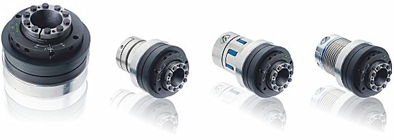
Torque Limiting Couplings

Protect mechanical equipment, or its work, from damage from mechanical overload.

Preventing Torque Overload with SAFEMAX® Torque Limiting Couplings

Torque overload is often unpredictable, and if not considered in machinery design, it can cause severe equipment damage, leading to extended and costly downtime. SAFEMAX® torque limiters are engineered to prevent such issues by instantly disconnecting the motor side from the driven side when a torque overload occurs. This rapid disengagement eliminates the risk of expensive downtime. Additionally, these limiters are torsionally rigid and backlash-free, allowing for quick and precise re-engagement once the overload cause is resolved.

Key Features

» Backlash-free torque transmission for accurate performance.
» Low moment of inertia to enhance efficiency.
» Compact and maintenance-free design for reliability.
» Ultra-fast disengagement within 1 to 3 milliseconds.
» Simple and safe torque adjustment.
» Automatic re-engagement
at 360° or in preset phase positions.
Equipped with regressive springs, these torque limiters ensure immediate disengagement within milliseconds during an overload. Once normal conditions resume, the limiter automatically re-engages at 360° or an optional preset phase, protecting the machine while maintaining seamless operation.

Benefits

Overload Protection
Torque limiters safeguard mechanical components by disengaging the drive when torque surpasses a preset limit. This prevents breakdowns caused by sudden load spikes or misalignments.

Reduced Downtime
Over-torque conditions can lead to equipment failure, requiring costly repairs and causing production delays. Torque limiters minimize these risks, ensuring continuous operation.

Extended Equipment Lifespan
By controlling excessive torque, these limiters reduce stress on connected machinery, prolonging the life of gears, bearings, and shafts.

Enhanced Safety
These couplings prevent the transmission of excessive forces, protecting both operators and machinery, particularly in high-speed or heavy-load applications.

Backlash Explained (using spider coupling as example).

Coupling backlash explanation, image 1, backlash.

Backlash

Backlash is the clearance or gap between the trailing or non-driving surfaces of the coupling jaws and flexible element, illustrated in red in the diagram.
When used in reversing or heavy cyclic applications, where the coupling is required to rotate in both directions, the application must be considered with the type of use, number of starts per hour considered and an appropriate service factor applied to  prevent premature failure of the coupling element. Standard spider 'teeth' are curved in two directions.
Coupling backlash explanation, image 2, non-backlash.

Non-Backlash

The coupling element and claw profile are designed such that  the element is compressed when the coupling is assembled in order to remove backlash, typical applications are for indexing or positioning drives such as lead screws or encoders where a  high  degree  of accuracy is required. The pre-compression or preload of the element whilst providing greater accuracy also increases the dynamic torsional stiffness from 25% to 75% over the standard element at 50% of it's nominal torque rating, (depending on coupling size), thus maintaining accuracy even after extended periods of use. Non-backlash spider 'teeth' are curved radially and parallel axially.
Specification of torque limiting couplings found in this on-line » catalogue « link
Questions?

Contact
jbj Techniques Limited
for friendly help and advice
telephone: +44 (0)1737 767493
email:
happy to help at jbj Techniques Limited, quality products for mechanical and fluid power
Return to top of page