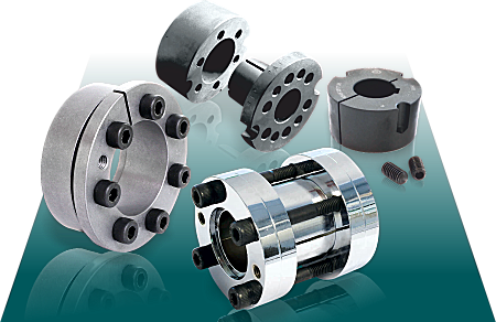
» Easy assembly and disassembly
Both actions take place by locking and unlocking the clamping screws with common tools. The use of a torque wrench is only necessary when a more precise torque is required.
» Superior holding power
The action of the clamping cones creates shaft clamping torque superior to a normal keyed hub.
» Overload protection
When the preset torque is exceeded SIT-LOCK® will slip, preventing the connected elements from being broken.
Note: SIT-LOCK® units are not friction couplings so, excessive slip will cause damage.
» Easy adjustment
Combining the SIT-LOCK design of smooth cone action with superior holding power, the hub can be clamped at any position along a shaft, eliminating the®need for lock washers, spacers, stop rings, etc.
» Precision location
With the SIT-LOCK® smooth cone action, the SIT-LOCK® is ideal for clamping cams, timing devices, and indexing mechanisms accurately and precisely. Temperature -20°C to 150°C.
» Unlimited use possibilities
SIT-LOCK® units are suitable to connect any type of hub (flywheels, chain-wheels, gears, levers, pulleys, eccentrics, coupling, etc).
» Various solutions in stock
Available in stock in 10 different types, SIT-LOCK® units can be utilized in a varied range of industrial applications.
A shaft to hub lock is critical in the design of a mechanical transmission as an unsuitable choice could cause serious damage to the machine or system and result in economic loss.
Shaft-hub coupling design considerations:
» Assessing application loads: torque, bending moment, axial force, radial force. Stresses that may occur simultaneously.
» Alternating loads, sudden starts and stops, very rapid acceleration.
» Fatigue limits of the coupling components.
» Suitable material use.
» Frequent installation and removal requirements.
» Fretting corrosion.
Traditional shaft-hub locking systems include:
» Feather keys
» Key
» Spline coupling
» Interference coupling: forced
Feather Keys
Feather key couplings are the most commonly used.
Assessing the disadvantages:
» High concentration of stress on the shaft and hub due to the high pressure generated on the keyway sides.
» Micro-movements caused by the lack of even contact can cause fretting corrosion making it difficult to remove.
» Not recommended for alternating loads. Over time, the pressure generated on the keyway sides can widen it and cause the shaft or hub to break. Not recommended in damp environments.
» The lack of contact over the shaft-hub surface may lead to oxidation, making it difficult to remove.
» Cannot accept axial loads.
» Not recommended for transmissions that require zero backlash.
» Significant decrease in shaft strength due to the keyway.
» Difficult axial and angular positioning.
Keys
Keyed shaft-hub couplings have the same disadvantages as feather key couplings and also cause significant hub-to-shaft concentricity error.
Splined Profile
This coupling has the following disadvantages:
» Fretting corrosion from the lack of contact making it difficult to remove.
» Significant decrease in shaft strength.
» Increased cost as it is difficult to make.
» Play between shaft and hub.
» Difficult angular and axial positioning.
» Not recommended in damp or dusty environments.
» Lack of contact may impair removal.
Interference Fit
Interference fit shaft-hub connections can be achieved by cooling the shaft or heating the hub.
This type of connection is not widely used for the following reasons:
» Requires tight tolerances.
» Difficult to remove.
» Locking area temperature changes.
» The effect of the centrifugal force created by the hub can decrease transmissible torque.
» Increased stress concentrated on the edges.
SIT-LOCK® Shaft Locking Device / Coupling
Simply by tightening the screws, SIT-LOCK® keyless locking devices create an axial force on the shaft and the hub that is spread over the entire contact surface. Unlike traditional systems. They offer numerous advantages.
Link to full technical specification catalogue for the
SIT-LOCK® Locking Device CouplingSIT-LOCK® Keyless Locking Elements Application Examples
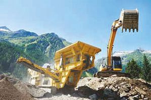
Locking a crusher flywheel using SIT-LOCK® 4.
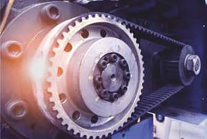
SIT-LOCK® 5A used for a timing belt pulley.
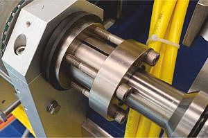
Nickel-plated SIT-LOCK® 10 locking two shafts.
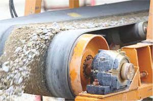
SIT-LOCK® 1 used for a conveyor belt pulley.
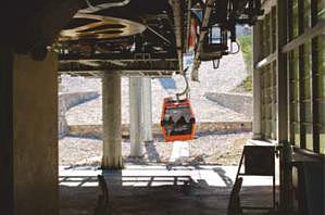
Locking the drive pulley of a cable car using SIT-LOCK® 4.
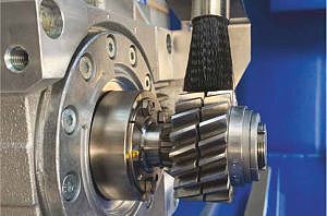
SIT-LOCK® 1422 used to lock a hollow shaft.
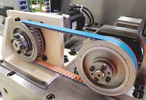
Mounting two pulleys using SIT-LOCK® 3 without spacers.
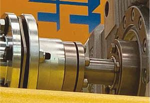
SIT-LOCK® 3 used for a disc coupling.
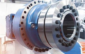
SIT-LOCK® 11 locking the hollow shaft of a planetary gearset.
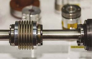
Locking a bellows coupling using SIT-LOCK® 16.

