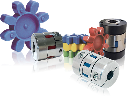
Types of Spider / Jaw Coupling Hub
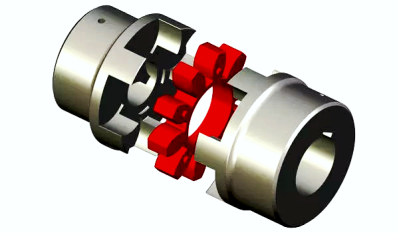
These spider / jaw couplings for mechanical power transmission are torsionally flexible shaft couplings, the operating characteristics of which are two hubs with concave claws, transmitting the torque by meshing with an elastic involute gear ring.
The spider coupling concept gives a reliable, smooth, power transmission without torsional oscillation / vibration and so protects the connected machinery.
Spider coupling with taper bushing
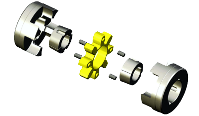
TRASCO® spider / jaw couplings type for taper bushing SER-SIT®, are manufactured in cast iron GG25.
They combine the typical high performances of standard TRASCO® spider couplings with the advantages of easy mounting and dismounting offered by the taper bushing SER-SIT®.
These hubs are manufactured in two different mounting executions:
B1: installing of tape bushing from outside.
B2: installing of taper bushing from inside (not available for size 90/100).
Spider coupling with shaft locking elements
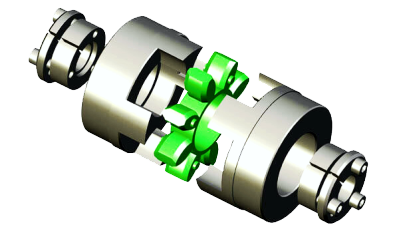
This execution has been introduced to incorporate advantages offered by the SIT-LOCK® CAL 8 locking elements in the shaft-hub connection.
The system allows for a quick, safe and backlash free mounting without the use of keyway and eliminating the need for lock washers, spacers and stop rings.
Many different solutions may be created to solve all kinds of application needs. We include hereunder a very useful example. In fact, the same hub bore allows the fitting of different shaft diameters.
Spider couplings with intermediate shaft
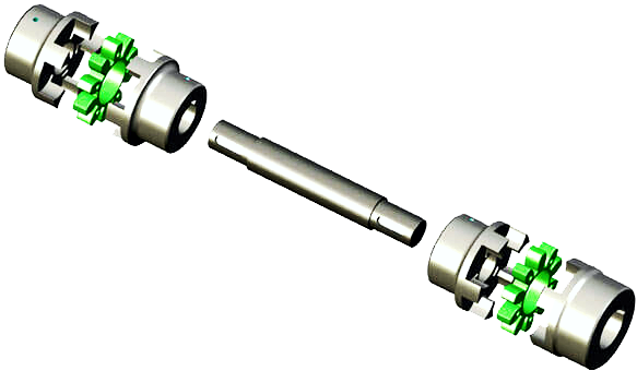
This spider coupling component set allows the joining of two shafts through two TRASCO® spider couplings and an intermediate shaft length of customized dimension.
The presence of two polyurethane rings allows high dampening capability and greater radial misalignments.
As a standard, hubs are made of cast iron, while shafts are from steel; though, different materials can be used, according to different applications.
Spider coupling with taper bushing
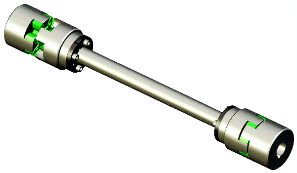
Combination of the previous two spider coupling component sets allowing the joining of two shafts through two TRASCO® spider couplings and an intermediate shaft length of customized dimension, mounted with shrink discs on the hubs.
The presence of two polyurethane elements allows high dampening capability and greater radial misalignments.
As a standard, hubs are made of cast iron, while shafts are made of steel; though different materials can be used according to different applications.
Flange mounted spider coupling
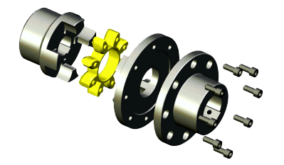
Spider coupling with flanges developed for applications on heavy machinery and to combine different shafts and flange solutions.
Compact flange spider coupling
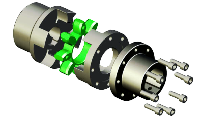
Similar characteristics as the previous example while being compact in dimension.
Double cardanic spider coupling
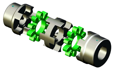
The cardanic setup allows compensation of high axial, radial and angular misalignment. The use of the double spider allows for twice the torsion angle and provides very high dampening effect.
Drum brake mounted spider coupling
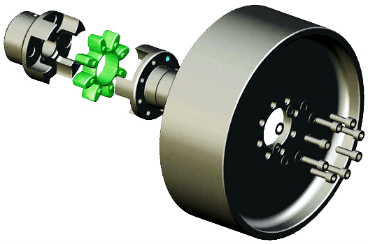
Developed to suit drum brake (FRT) transmission. An elastic coupling consisting of:
» Standard hub (any of Trasco spider coupling range).
» Elastic spider.
» Special hub attached to brake drum.
Also, assembling of different dimensioned brake drum to any kind of coupling is allowed.
Brake disc mounted spider coupling
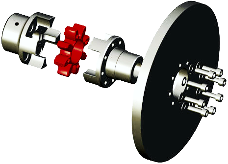
Developed to suit disc-brake (FRD) transmissions.
An elastic coupling consisting of:
» Standard hub (any of Trasco spider coupling range).
» Elastic spider.
» Special hub attached to the brake disc.
Also, assembling of different dimensioned brake discs to any kind of coupling is allowed.
'Ultra temperature' spider inserts
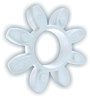
Overcome harsh environmental factors from below freezing to blistering heat, UV exposure, and the detrimental effects of salt water.
» Larger Continuous Temperature Range.
» Higher Nominal & Max Torque.
» Superior Hydrolysis Resistance.
Link to
pdf document
Due to the complete
flexibility and
ductility of the elastomer ring, it
compensates for parallel and angular
displacements as well as to
absorb longitudinal movement of the shafts.
G Series Jaw Couplings, Gravity Die-Cast using LM25 Aluminium Alloy
Manufactured in the UK to jbj Techniques' proprietary patterns, G Series jaw couplings are expertly gravity die-cast using LM25 aluminium alloy. This process ensures robust and durable castings with superior strength and reliability. Unlike injection-cast alternatives, which are prone to porosity and compromised structural integrity, gravity die-casting produces components of consistently high quality, designed to perform under demanding conditions.
Each coupling is precision-machined finished at jbj’s well equipped machine shop facility to meet specific customer application requirements. Combined with the correct Shore hardness elastomer element, these jaw couplings are ready to efficiently transmit mechanical power across a wide range of machinery applications.
Link to G Series Coupling Data Sheets pages 18 to 21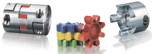


Available on request spiders with different compound for special applications:
» High working temperature.
» Heavy working conditions.
» Heavy environment conditions.
» Resistance to specific chemicals.
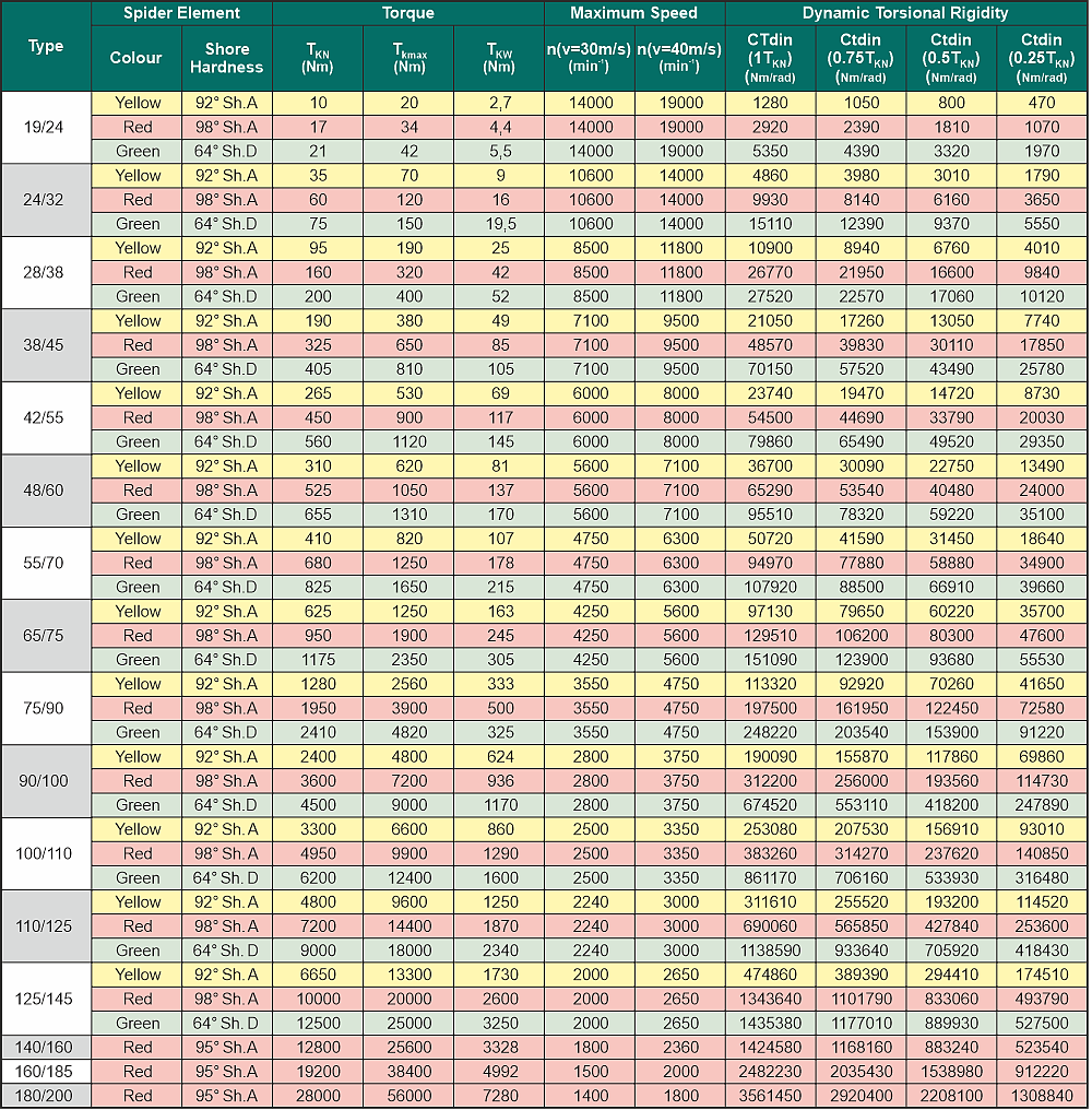
The involute teeth of the elastomeric inserts are crowned in order to avoid edge pressure on the tooth flanks and so avoid undesirable axial thrust. The puncture proof spider coupling can be loaded extremely high since the elastic elements are submitted to compression and not to bending moments of force. The elastomer gear ring, made of a newly developed polyurethane of various degrees of shore hardness, has important advantages in comparison with the standard polyurethanes. It is non-ageing, with resistance against hydrolysis (can be used in tropical conditions), non-abrasive, has a high self-damping effect and is also
resistant to oil and ozone. It can be used with temperatures ranging from
-40°C to +120°C.
Spider / jaw mechanical power transmission couplings can be used for horizontal as well as for vertical shaft connections, for reversing, intermittent service and are electrically insulating. The operating characteristics and the durability of the coupling are very positively influenced by the high overall precision of the machining, especially the claws, unbalance is reduced to a minimum, running is improved and service life considerably increased.
Scroll down this page for
specification catalogues (link) for straight jaw spider couplings and jaw in-shear type couplings.
Application service factors for the spider / jaw coupling
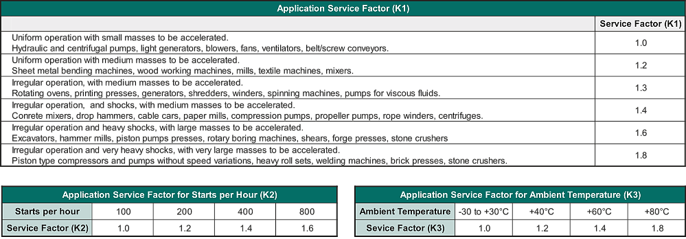
Total service factor for K = K1 x K2 x K3
What is a service factor for mechanical power transmission couplings?
For mechanical power transmission couplings, the service factor is a
multiplier used to properly size a coupling for an application's specific operating conditions. (
See above tables) It accounts for real-world factors like shock loads, torque fluctuations, and the type of equipment being connected, all of which affect the coupling's expected lifespan.
Instead of using just the motor's power (kW) to select a coupling, the power of the design is calculated by multiplying the motor's power by a service factor. This ensures the coupling is robust enough to handle the actual demands of the application.
Factors affecting a coupling's service factor
Several application-specific characteristics determine the service factor needed:
Prime Mover Characteristics: The type of engine or motor driving the system affects the consistency of torque delivery.
» Electric motors: Deliver relatively smooth, uniform torque.
» Reciprocating engines: Produce rough, cyclic torque fluctuations.
Driven Equipment Characteristics: The equipment being powered creates its own unique load profile.
» Centrifugal pumps: Have a relatively uniform torque requirement.
» Reciprocating pumps or compressors: Create significant torque fluctuations throughout their operating cycle.
Load Conditions:
» Shock loads: Applications with frequent starts and stops or heavy impacts, like metal crushers or vibrating screens, require a higher service factor.
» Non-uniform loads: An application that experiences frequent changes in load will require a higher service factor.
Operating schedule: Applications that run continuously for many hours a day require a higher service factor than those that operate only intermittently.
Environmental conditions: Factors like elevated temperatures or harsh environments can also influence the required service factor.
Calculating the required torque for a coupling
To select the right size coupling, you use the service factor to calculate the "design torque" or "design power" that the coupling must handle.
Calculate the rotating drive torque using a basic formula:
Torque (Nm) = Power (kW) x 9550*/Speed (RPM), * 9550 is a constant derived from power (W) and speed (rad/s).
Formula
Design Torque = (required torque for application) x (service factor).
Example
For a pump requiring 50 Newton metres (Nm) of torque, the coupling manufacturer's manual might recommend a service factor of 1.2. The selection is then made based on the higher design torque:
50 Nm x 1.2 = 60 Nm
The user must then select a coupling with a nominal torque capacity equal to or greater than 60 Nm.
Important considerations
Don't ignore the service factor: Improperly sizing a coupling by ignoring the service factor can lead to premature wear and premature failure of components.
"Weak link" design: In many applications, the coupling is designed to be the "weak link" in the power transmission system. This ensures that if a failure occurs due to extreme loads, the coupling breaks first, protecting more expensive components like the motor or gearbox.
Manufacturer data is key: Always use the service factor values and sizing procedures recommended in the specific coupling manufacturer's catalogue.


